Virtual Reality Haptics
Created a wearable haptic device for virtual reality. Demonstrated device by creating a virtual drum kit.
Overview
This project is an exploration in designing and programming robotic systems for VR haptic feedback. The main selling point of VR is the immersion. However in current systems, the immersion is only an audio-visual experience. Integrating the sense of touch is the next step in immersion. Haptic feedback can enable more complicated applications such as telerobotic surgery and strengthen well developed applications such as gaming. VR haptic gloves were the first expansion into the tactile domain. These gloves can resist finger motion. This project is concerned with resisting wrist and arm motion.
Initial Design
In this project, we worked backwards from the end goal. Our goal was to deliver force/torque feedback to user's wrist and arm. We began by thinking about mechanical systems to could produce significant force/torques on the user's arms. Our plan was to use motor(s) to generate torque and use a linkage to convert the torque into a force or torque felt by the user. The best way to visualize this is by imagining a robotic arm in which the user is holding the end effector (Figure 1). Actuating the motors in the robotic arm, will extert torques/forces on the user's hand. If this robotic arm is stationary in the room, the VR experience is confined to the arm's workspace. If the robotic arm is attached to the user, the VR experience if fully mobile. There are two main complications to this design. The user must carry the weight of the robot, and the user's body must disperse the reaction forces (the base of the robot will exert forces on the user).
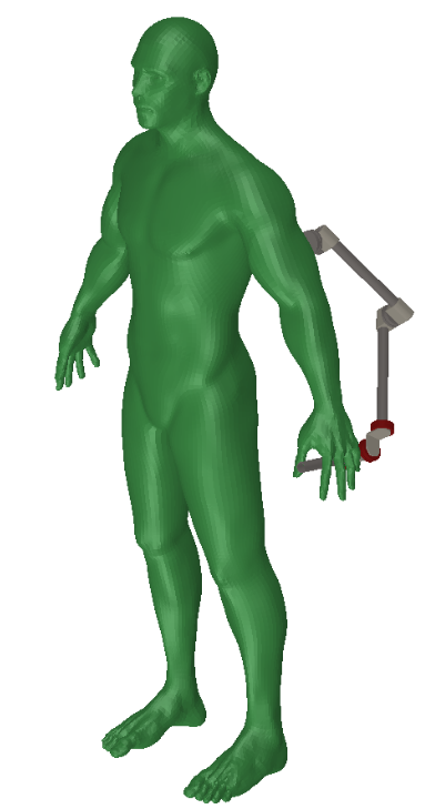
Figure 1. Rendering of the theoretical device initially designed. Motors in the linkage could be actuated to exert torques/forces on the user's wrist and arm.
From a software and controls standpoint, the primary concern is the VR tracking frequency. The maximum stiffness of a haptically rendered surface depends on the speed of the controller. The Valve Index, comes with a state of the art tracking system, SteamVR Base Station 2.0. This tracking system provides data at 144 Hz. This project addresses the following research question. Given a tracking frequency of 144 Hz, what surfaces can be haptically render? The answer to this question is based in both engineering and human psychology.
Materials
Hardware Selection
As mentioned, I am using a Valve Index with the SteamVR Base Station 2.0. The other primary components needed are motors, encoders, and a motor driver. I decided to use the T-Motor GL60 KV25. I chose this motor for the following reasons. It can deliver high torque at low currents which helps prevent the motor from overheating. It has a has 14 pole pairs, so rotation is smooth. This is necessary to create compelling haptics. It weighs 230g which is reasonable for the heaviest component of the wearable device. For the motor driver, I decided to use the ODrive. This motor driver is open-source, so it can be modified if needed. Also, the ODrive implements field oriented control to smoothly control the motor. I am using the AS5048A encoder. This encoder has 14-bit resolution and is supported by the ODrive.
Software Selection
It was difficult to select the software to use for this project. Robots run on Linux, whereas VR runs on Windows. I settled on using Linux for the following reasons. This project is primarily a robotic technology exploration not a VR technology exploration. The robotics side of this project will be easier to build upon in the future if this foundation is built Linux. Once the technology is no longer experimental, it can be ported Windows. The downside to using Linux, is that it is difficult to interact with the VR hardware. Currently, popular game engines, Unity and Unreal Engine, do not support VR development in Linux. I decided to use the OpenXR API directly to interact with the hardware. I stripped down an OpenXR example render pipeline for my own use. This project focuses on the sense of touch, so for now I am not rendering to the VR headset. I am only using the VR setup and render pipeline to access the controller tracking data.
Pipeline
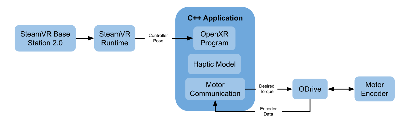
Figure 2. General software architecture. The application inputs the controller pose and encoder data. The haptic model determines the torque that should be applied to the motor. The desired torque is sent to the ODrive. The ODrive directly controls the motor.
VR Input
The SteamVR Base Station 2.0 samples controller and headset poses.
The SteamVR runtime converts the data from the SteamVR Base Station into meaningful information.
The OpenXR program collects both controller poses as well as the headset pose.
Note on SteamVR Runtime: This is currently the only runtime that can interact with the SteamVR Base Station 2.0.
SteamVR is closed source, and their developement practices (specifically for Linux) are questionable.
For this project, I am using SteamVR version 1.15.12. Also, I disabled SteamVR from connecting to the internet.
This is the only way to prevent auto updates.
I recommend using
Monado,
an open-source runtime, when SteamVR Base Station 2.0 is supported.
C++ Application
OpenXR Program
This part of my application was derived from the
hello_xr OpenXR example.
I simplified this code to only the portions needed for this project.
I also added functionality to query the state of the program and retreive necessary information such as controller pose.
Haptic Model
The haptic model uses the controller pose and encoder data to calculate the torque that should be applied to the motor.
The code is structured to make the haptic model easily modifiable.
This allows developers to easily experiment when attempting to render various surfaces and textures.
Motor Communication
The ODrive comes with a Python-based CLI that serially communicates with the motor driver.
Since my application requires C++ for OpenXR, I implemented a
motor communication library
in C++ enabling direct communication with the ODrive.
Motor Control
After the C++ application sends a desired torque to the ODrive, the ODrive's control algorithms should handle the direct motor control. However, I had to modify the hardware and software on the ODrive to enable the torque control mode. The ODrive firmware classifies motors into two categories, high current motors and low current motors. The T-Motor GL60 KV25 is classified as a low current motor. The ODrive does not implement torque control for low current motors because it can overheat the ODrive and/or the motor. To work around this, I replaced the standard shunt resistors on the ODrive with 0.02Ω resistors. I also modified the shunt resistance value in the firmware to reflect this change.
1 Degree of Freedom
Since this project is novel in the domain of VR haptics, I started with a single degree of freedom system.
There were two goals during this stage of the project. The first was to implement the software pipeline previous mentioned.
The second goal was to assess the ability to haptically render surfaces using encoder data and using VR tracking data.
The plan was to haptically render a wall using the model of a spring. Hooke's Law states: $$F_s = -kx$$
\(F_s\) is the spring force [N]
k is the spring constant [N/m]
x is the displacement [m]
My system only produces torque, so I modified the equation.
$$T_m = -kθ$$
\(T_m\) is the motor torque [Nm]
k is the spring constant [\(\frac{Nm}{degrees}\)]
\(θ\) is the displacement [degrees]
VR Tracking vs. Encoder Feedback
The C++ application received encoder data at a frequency of 490 Hz. Using only the encoder feedback I was able to render walls with very high stiffness and little instability. Instability only occured when the user held the controller exactly at the wall boundary. The VR tracking data came in at 144 Hz. Using the tracking data feedback I was able to render walls at low stiffness with little instability. At this low stiffness the "wall" did not feel like a wall. At medium stiffness there was significant instability at the wall boundary, but the wall felt realistic.
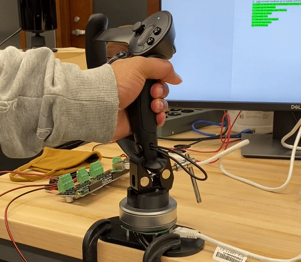
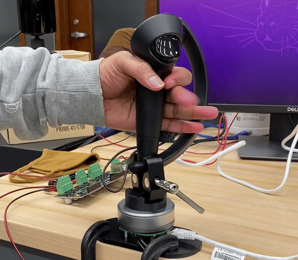
Figure 3.
The left is a rendered wall with stiffness 2 \(\frac{Nm}{deg}\) using encoder feedback.
The right is a rendered wall with stiffness 0.2 \(\frac{Nm}{deg}\) using tracking feedback.
The encoder produces minimal jitter at the wall boundary, but the tracking data produces significant jitter.
Determining the Cause of Instability
The results above did not confirm that compelling haptics are feasible given the bottleneck tracking frequency. In order to create compelling haptics using the tracking data, I needed to determine the cause of the instability. I did this by limiting the encoder data frequency to 144 Hz. Even with a throttled frequency there was not significant instability at the wall boundary. Then, I added gaussian noise to the encoder data. Doing this made the walls rendered using encoder data feel like the walls rendered using VR tracking data.
Filtering
Due to the noise in the tracking data, I decided to filter the controller pose.
I used the following exponential smoothing function as a low pass filter:
$$s_0 = x_0$$
$$s_n = αx_n+(1-α)s_{n-1}$$
s is the filtered output
x is the unfiltered input
\(α\) is the smoothing factor
I qualitatively determined \(α=0.5\) to be the optimal smoothing factor.
You can find the class I made for exponential smoothing
here.
The results convinced me that compelling haptics are feasible using the SteamVR Base Station 2.0
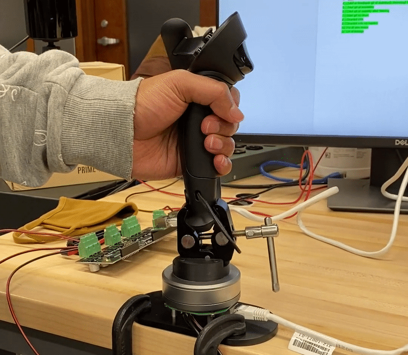
Figure 4. Rendered wall with stiffness 0.2 \(\frac{Nm}{deg}\) using filtered tracking feedback. There is still some instability at the wall boundary, but it has been significantly reduced
2 Degrees of Freedom
The 1 degree of freedom system confirmed that compelling haptics are feasible.
The next step was to incorporate more freedom of movement.
I put the 1 degree of freedom system on a vertical slider to make a 2 degree of freedom system.
Haptics in the 2 degree of freedom system cannot be done with just the encoder.
The VR tracking data is necessary to determine the position of the controller.
The VR tracking data or the encoder data could be used to determine the angle of the controller.
In this system, I decided to haptically render a ceiling.
You can imagine the VR controller as a drumstick (extending past the top of the physical controller), and the drumstick tip (cursor) is interacting with the ceiling.
As the cursor touches the ceiling, the motor delivers a torque that prevents the drumstick from penetrating the ceiling.
I used the following equation to model the ceiling:
$$T_m = -kx$$
\(T_m\) is the motor torque [Nm]
k is the spring constant [\(\frac{N}{m}\)]
x is the depth of the cursor into the ceiling squared [\(m^2\)]
This equation allowed me to express the spring constant in traditional units.
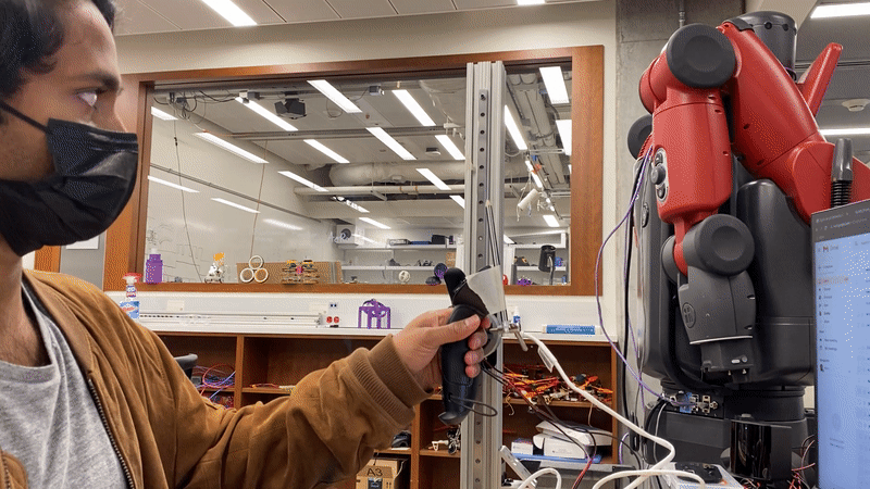
Figure 5. Rendered ceiling with stiffness 700 \(\frac{N}{m}\) using a combination of filtered tracking feedback and encoder feedback.
6 Degrees of Freedom
The next step was to detach the controller from the vertical rail. In order to do this, the system needed to become a wearable. My advisor, Bill Strong, designed and manufactured an arm brace for haptic feedback. The arm brace disperses motor reaction forces through the user's forearm. This wearable allows the user the move and orient the controller in 3D space.
Linkage
A notable feature of the haptic device, is the four bar linkage that attaches the motor to the VR controller. This linkage provides room for the controller to move vertically without rotating the motor. However, controller rotation requires motor rotation and vice versa. Therefore, the haptic controls are not significantly affected. The lever arm between the motor and controller is longer, so the user feels slightly less torque. But, the longer lever alligns the motor with the user's wrist. This linkage makes the wearable feel comfortable and natural even though the user can only easily utilize 4 of the typical 6 degrees of freedoms.
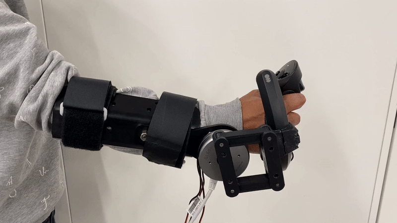
Figure 6. Wearable haptic device that can exert a torque about the axis through the user's wrist.
Initial Tests
The software for 2 degree of freedom could be used for the new 6 degree of freedom system with minor changes and constraints. First I changed the haptically rendered ceiling to a haptically rendered floor. I assumed the floor has infinite length and width. I did not rotate the controller about the axis in line with my arm. This allowed me to test the wearable without significantly modifying the software. When using the haptic device, it felt almost exactly like a drum. I decided to focus on making a virtual drumming demonstration with haptics. Haptics projects are difficult to portray in videos, so hopefully the example of a drum will help the viewers of this post potentially understand the feeling of the device and some of its applications.
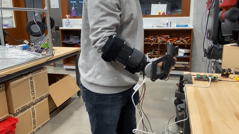
Figure 7. Initial tests of the haptic device. The haptic model transferred from the 2 degree of freedom system made the suface feel like a drum
Drum Kit Haptic Model
After testing the haptic device, I started to modify the software to fully utilize all 6 degrees of freedom. In the 2 degree of freedom system, tracking the cursor (or drumstick tip) was simple trigonometry. All you needed to know was the controller height and angle. In the 6 degree of freedom system, tracking the cursor is more complicated. I set up transformation matricies to define a world frame and track the controller and cursor frames. I defined the world frame using the initial controller pose when the program starts. The controller is then tracked in reference to the world frame. The cursor is defined as a static transformation from the controller frame. Therefore, the controller and cursor move together. The final step was to define drum surfaces. I created a drum object in C++. The rectangular volume of each drum is defined using a center coordinate (x,y,z), a lenth, and a width. The surface starts at the center z coordinate, and extends downward infinitely. Each drum surface has an associated spring constant to simulate different drums. The drum objects also contain methods and parameters that are used for drum systhesis.
Drum Synthesis
In order to make a virtual drum demonstration, I needed to synthesize a drum sound. To do this, I used Pure Data. Pure Data is an open-source visual programming language that specializes in audio digitial signal processing. In Pure Data, I used samples of various drums and played the sample everytime the cursor contacted the drum. To make the sound more realistic, I multiplied the sampled drum sound with an ADSR (attack, decay, sustain, release) envelope. I used parameters from my application to modify the envelope. The cursor velocity amplifies the drum sound. The cursor/drum contact point determines the sustain of the drum sound. For example, if you hit the drum as hard as you can directly at the center point, the drum sound is loud and sustains for a long time. I implemented a communication protocol and utilized a TCP port to send data from the C++ application to the drum synthesizer.
Conclusion & Next Steps
This project is a succesful step into VR haptics beyond the fingertips. Going back to the initial research question, "Given a tracking frequency of 144 Hz, what surfaces can be haptically render?" For wrist haptics, there are many possibilites for haptic rendering at this frequency. In my opinion, the controller instability became noticeable at stiffness values greater than 800 \(\frac{N}{m}\). At this stiffness, a virtual wall feels realistic to the cautious user. Rendering a wall in the headset could discourage users from testing the stiffness of the wall. While 800 \(\frac{N}{m}\) is the max stiffness I achieved, there are methods that could potential increase the stiffness. One feature I did not get to implement is concurrency in the system. The application can receive data from the encoder at 490 Hz, but in my implementation the frequency is capped at 144 Hz because of the render loop. By obtaining encoder data in a separate thread, the controller tracking frequency can be artifically increased via sensor fusion. The spring model was ideal for a drum, but the equation could be changed for different effects. Damping makes surfaces feel less elastic. In my experimentation, the cursor velocity needs aggressive filtering for a compelling damping effect. Textures are also possible. For example, the act of drawing the blinds exerts small forces on your wrist that can be simulated.
This project provided insights on how to proceed for full arm haptic feedback. One thing I learned from the arm brace, is that bearing the weight of a robotic arm with is not feasible. The arm brace is comfortable, but the weight of the brace becomes a nuisance after 10-15 minutes. When designing full arm haptic devices, it would be best to apply the force from a distance. In this case, another part of your body such as your hip could bear the weight of the heavy components as your arm receives the force feedback. Moving forward, I no longer have access to the hardware necessary for this project, but hopefully this post provides insights for future developers.
Acknowledgements
Bill Strong came up with the initial ideas that started this project.
He also helped during every step of this project.
The majority of mechanical design demonstrated throughout this project is his work.
Matthew Elwin gave guidance and insights throughout this project.
Specifically, he helped me and Bill stay focused on the primary goal.